This tutorial part, I'm introducing a clean way to add compute or fullscreen pixel passes with RDG API and without touching UE5 engine code at all. Everything lives inside our own module.
Adding a module
- follow the generic guideline to prepare a customized module from Unreal Official https://docs.unrealengine.com/5.2/en-US/how-to-make-a-gameplay-module-in-unreal-engine/
- in MyProject.uproject, set "LoadingPhase" to "PostConfigInit" because we want the shader module to be loaded immediately after config system has been initialized and before engine is been fully initialized.
- in MyModule.h make sure FMyModule class inherit from public IModuleInterface, then you can implement essential overridable functions like StartupModule and ShutdownModule.
- in MyModule.cpp the implementation of FMyModule::StartupModule(), map the actual shader folder on your disk to a virtual path.
FString ShaderDirectory = FPaths::Combine(FPaths::EngineDir(), TEXT("Shaders/"));
AddShaderSourceDirectoryMapping("/CustomShaders", ShaderDirectory);
- Don't forget IMPLEMENT_MODULE(FMyModule, ModuleName) Macro in MyModule.cpp
Compute pass example
Prepare shader class
- make another cpp and h files (MyShaderHandler.cpp & MyShaderHandler.h). we need a FGlobalShader class, which you can imagine as an binding bridge between UE5 and HLSL.
// interface between engine and HLSL shader
class FMyShaderClass: public FGlobalShader
- create a shader parameters struct (same as parameters in shader) For example let's look at a simple compute shader just writing a debug texture:
ExampleCS.usfRWTexture2D<float4> OutputTexture; float DebugValue;[numthreads(THREADGROUPSIZE_X, THREADGROUPSIZE_Y, THREADGROUPSIZE_Z)] // this 3 values will be set from C++ side in our global shader classvoid MainCS(uint3 Gid : SV_GroupID, //atm: -, 0...256, - in rows (Y) --> current group index (dispatched by c++) uint3 DTid : SV_DispatchThreadID, //atm: 0...256 in rows & columns (XY) --> "global" thread id uint3 GTid : SV_GroupThreadID, //atm: 0...256, -,- in columns (X) --> current threadId in group / "local" threadId uint GI : SV_GroupIndex) //atm: 0...256 in columns (X) --> "flattened" index of a thread within a group) { OutputTexture[DTid.xy] = float4(0, DebugValue, 0, 1); }in our shader class, these macros are creating equivalent parameters to our shader example, so later on we can bind them and set values. In Unity we reply on make a string name or int representation. If you feel uncertain about what each macro mean, check for their declarations in ShaderParameterMacros.hpublic: DECLARE_GLOBAL_SHADER(FMyShaderClass); SHADER_USE_PARAMETER_STRUCT(FMyShaderClass, FGlobalShader); BEGIN_SHADER_PARAMETER_STRUCT(FParameters, ) SHADER_PARAMETER(float, DebugValue) SHADER_PARAMETER_RDG_TEXTURE_UAV(RWTexture2D, OutputTexture) END_SHADER_PARAMETER_STRUCT()
-
set correct shader permutation for the platform you want to run on (same concept as shader variations in Unity) note: RHI is a graphics layer on top of various lower level Graphics APIs in UE5
static bool ShouldCompilePermutation(const FGlobalShaderPermutationParameters& Parameters) { return IsFeatureLevelSupported(Parameters.Platform, ERHIFeatureLevel::TYPE); } - set thread group count (some places call them work group size) from our shader class to HLSL
static inline void ModifyCompilationEnvironment(const FGlobalShaderPermutationParameters& Parameters, FShaderCompilerEnvironment& OutEnvironment) { FGlobalShader::ModifyCompilationEnvironment(Parameters, OutEnvironment); OutEnvironment.SetDefine(TEXT("THREADGROUPSIZE_X"), NUM_THREADS_PER_GROUP_DIMENSION); // NUM_THREADS_PER_GROUP_DIMENSION is just a macro user defined OutEnvironment.SetDefine(TEXT("THREADGROUPSIZE_Y"), NUM_THREADS_PER_GROUP_DIMENSION); OutEnvironment.SetDefine(TEXT("THREADGROUPSIZE_Z"), 1); } - config shader class with correspondent HLSL file and the kernel to execute (right outside of our shader class). Now we have our shader class ready!
IMPLEMENT_GLOBAL_SHADER(FMyShaderClass, "/CustomShaders/ExampleCS.usf", "MainCS", SF_Compute);
Bind Parameters and attach pass to unreal renderer
- bind parameters. Don't worry about PostOpaqueRenderParamters for now, it's a built-in UE5 render event parameter, we will get into that later.
To config and dispatch our shader, let's create another class FCSDispatcher which implements our module API MODULENAME_API.
There are a few things I would like to explain for those get irritated if don't understand what's behind the scene (me too), if you're comfortable with black box feel free to ignore this:
first, MODULENAME_API is automatically generated by Unreal build tool UEBuildModuleCPP.cs at Definition.MyProject.h as #define COMPUTESHADER_API DLLIMPORT (somehow in Riders search doesn't work for DLL files, if you know how to config teach me svp!).
Second, as you can see the below code we use FRDGBuilder and FRDGTexture, RDG is render graph API 1 level higher than RHI. It packs command lists to graph data structure, it has other advantages like executing passes in parallel. This is a good and brief diagram found in the hyperlink: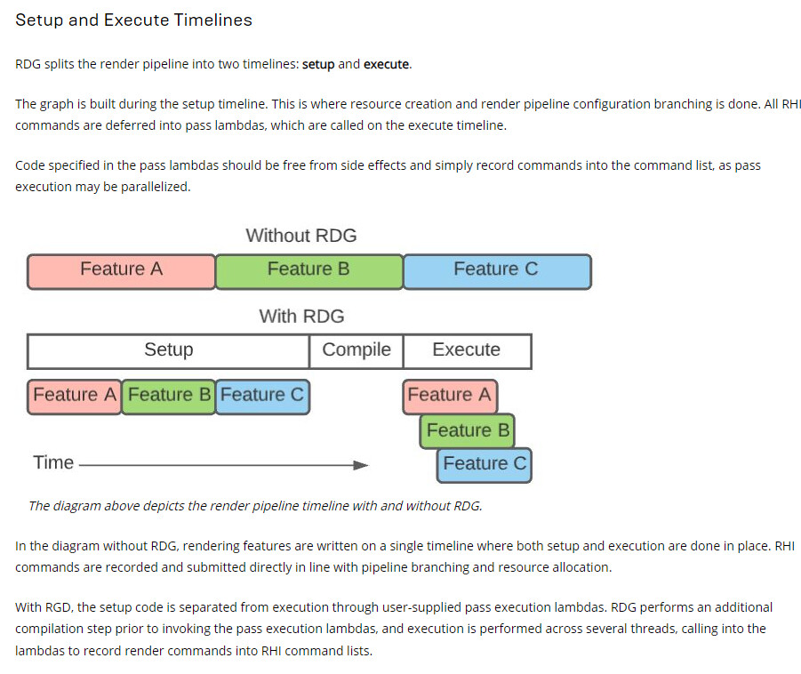 Third, the delegate in our dispatcher class is to hook onto Unreal's renderer callback event. This way we don't pollute engine code with our passes. If you don't fully understand, don't worry, you will see more details later. BeginPass is to register the our delegate and EndPass is to remove our pass from it.
 class MODULENAME_API FCSDispatcher { public: FCSDispatcher(); FRDGTextureUAV* ComputeOutput; void BeginPass(); void EndPass(); private: FDelegateHandle OnPostOpaqueRenderDelegate; void AddComputePass(FPostOpaqueRenderParameters& PostOpaqueRenderParameters); }; - in AddComputePass, bind objects/values to shader parameters:
FRDGBuilder& GraphBuilder = *PostOpaqueRenderParameters.GraphBuilder; TShaderMapRef<FMyShaderClass> ComputeShader(GetGlobalShaderMap(GMaxRHIFeatureLevel)); // get reference to our shader in shadermap // create UAV FRDGTexture* Texture = GraphBuilder.CreateTexture(FRDGTextureDesc::Create2D(FIntPoint(1920, 1080), PF_R8, FClearValueBinding::Black, TexCreate_UAV), TEXT("ComputeOutput")); ComputeOutput = GraphBuilder.CreateUAV(FRDGTextureUAVDesc(Texture, 0)); // bind pass parameters FMyComputeShader::FParameters* PassParameters = GraphBuilder.AllocParameters<FMyComputeShader::FParameters>(); PassParameters->OutputTexture = ComputeOutput; PassParameters->DebugValue = 1; - Then attach our pass to RDG graph builder by AddPass, AddPass function attach and execute the pass to command list every frame, it doesn't mean our pass will be added repeatedly as the name AddPass might suggest. Another thing to note is ERDGPassFlags::NeverCull, normally this flag is unnecessary. In Unreal RenderGraphBuilder.cpp, a pass will be automatically culled if none of the output resource is used somewhere (for example texture used as fullscreen output or attach to a material of some objects). If a pass is culled, renderer will throw an assertion error and crash immediately. Here for demonstration purposes I just temporarily tell the renderer not to cull our pass.
FComputeShaderUtils::AddPass( GraphBuilder, RDG_EVENT_NAME("My COMPUTE PASS"), ERDGPassFlags::Compute| ERDGPassFlags::NeverCull, ComputeShader, PassParameters, FIntVector(FMath::DivideAndRoundUp(1920, NUM_THREADS_PER_GROUP_DIMENSION), FMath::DivideAndRoundUp(1080, NUM_THREADS_PER_GROUP_DIMENSION), 1) ); - Register and unregister render pass to a proper render module in Unreal. FPostOpaqueRenderParameters and OnPostOpaqueRenderDelegate. PostOpaqueRender is a render event provided by Unreal renderer. You can go through Unreal's render pipeline to find proper sequence for your pass to be executed. Once we add our delegate to PostOpaqueRenderDelegate, our pass will be called everytime in RenderPostOpaqueExtensions, and RendererInterface will pass PostOpaqueRenderParameters to our function. see the internal delegate declaration of FPostOpaqueRenderDelegate. With PostOpaqueRenderParameters you can access to many useful screen render resources.
FPostOpaqueRenderDelegate
DECLARE_MULTICAST_DELEGATE_OneParam(FOnPostOpaqueRender, class FPostOpaqueRenderParameters&)
Now it should be obvious enough to look at BeginPass and EndPassvoid FCSDispatcher::BeginPass() { if(OnPostOpaqueRenderDelegate.IsValid()) return;; OnPostOpaqueRenderDelegate = GetRendererModule().RegisterPostOpaqueRenderDelegate(FPostOpaqueRenderDelegate::CreateRaw(this, &FCSDispatcher::AddComputePass)); }void FCSDispatcher::EndPass() { GetRendererModule().RemovePostOpaqueRenderDelegate(OnPostOpaqueRenderDelegate); }

Full-screen rasterization pass example
Prepare shader class
this step is the same as the instruction of making a shader class in compute shader pass part, only thing special is to be able to bind our fragment shader output to renderer, add the following macro when declare shader parameters.
RENDER_TARGET_BINDING_SLOTS()
Add a full screen pass
- bind paramters: nothing very special except with the macro we wrote in shader parameter declaration, we now have access to RenderTargets array, and here we are binding it to screen color texture PostOpaqueRender provides.
FMyPostProcessingShader::FParameters* PixelPassParameters = GraphBuilder.AllocParameters<FMyPostProcessingShader::FParameters>();
PixelPassParameters->Test = 1;
PixelPassParameters->RenderTargets[0] = FRenderTargetBinding(PostOpaqueRenderParameters.ColorTexture, ERenderTargetLoadAction::ENoAction);
- attach full screen pass
TShaderMapRef<FMyPostProcessingShader> PixelShader(GetGlobalShaderMap(GMaxRHIFeatureLevel));


FPixelShaderUtils::AddFullscreenPass(
   GraphBuilder,
   GetGlobalShaderMap(GMaxRHIFeatureLevel),
   RDG_EVENT_NAME("My PIXEL PASS"),
   PixelShader,
   PixelPassParameters,
   PostOpaqueRenderParameters.ViewportRect
   );
Handy Notes:
- to hot reload shader after some modifications: run recompileshaders changed in console
References
https://medium.com/realities-io/using-compute-shaders-in-unreal-engine-4-f64bac65a907
https://sites.google.com/view/arnauaguilar/projects/computeshader-ue5
https://www.froyok.fr/blog/2021-09-ue4-custom-lens-flare/#step_1_setting_up_a_plugin
https://itscai.us/blog/post/ue-view-extensions/#mycustommodulecpp-and-mycustommoduleh
https://mcro.de/c/rdg#pass-parameters
https://thegraphicguysquall.wordpress.com/2022/04/23/ue4-27-hello-ray-tracing/